Definition of windlass
1. The windlass is used as a machine for breaking down and lifting anchors, and the rollers on it can be used for twisting cables.
2. Machinery for retracting and releasing anchors and chains on ships.
3. Anchor windlass for short. It is a machine used to drop anchor, lift anchor, retract anchor chain and double as mooring mooring.
4. The anchor cable (anchor chain or wire rope) and the deck machinery of the anchor are released or retracted, and it is also the device that ties the ship when the anchor is dropped.
What is the windlass, the role of the windlass!
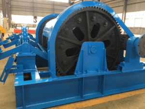
The windlass is mainly composed of sprocket shaft, anchor chain wheel, winch drum, clutch, transmission mechanism and brake mechanism. According to the power, there are manpower, electric and hydraulic; according to the mechanism, there are vertical and horizontal. The sprocket shaft is arranged horizontally, and there are one or two anchor sprockets for lifting single and double anchors, and the winching drum is used for winding cables. The chain pulley, the winch drum and the sprocket shaft are connected or disengaged by a toothed clutch. The braking mechanism is used to control the retracting and unwinding speed of the anchor chain. The manpower windlass is used for small boats or for emergency backup. Generally, ships are equipped with a windlass, which can lift and drop the left and right anchors separately or at the same time, and can also winch cables. It is usually installed on the deck of the first floor of the ship. It is reversed and has sufficient power, and is now widely used in combination windlass that uses only one unit for various operations such as anchor lifting, mooring, and cable pulling.
The windlass uses manpower, steam engine, electric motor, hydraulic motor, etc. as power. Usually installed on the bow deck of a ship. Its development trend is to use one unit to realize operations such as anchor lifting, mooring, automatic mooring and cable tie.
Windlass can be divided into two categories according to the direction of their main shaft (the shaft on which the sprocket or roller is installed), namely horizontal windlass and vertical windlass, the latter also known as anchor (mooring) winch. Horizontal windlass usually refers to windlasses equipped with sprockets, which can be divided into double-sprocket horizontal windlasses and single-sprocket horizontal windlasses, the latter also known as single-sided horizontal windlasses.
Anchor windlass are mechanical devices for dropping, lifting, and twisting cables. The windlass whose sprocket shafts are arranged horizontally is called horizontal windlass, which is commonly used by merchant ships; the vertical windlasses are called vertical windlasses, which are mostly used in warships. According to different power, it is divided into three types: electric windlass, hydraulic windlasses and steam windlasses, with roughly the same structure. Electric windlasses are widely used in internal combustion engine ships. Steam windlasses are rarely used on seagoing ships. For fire and explosion protection, steam windlasses are also used on oil tankers.
The windlass can cast and lift the left and right anchors at the same time or separately; it can simultaneously win the double anchors from a depth of not less than 45m; the clutch can be operated by one person; there is a reliable braking device; Throwing, and can stop at any time.
Small and medium-sized ships are generally equipped with double sprocket horizontal windlasses; large ships, especially ships with larger bow deck widths, are more suitable for single-sided (single sprocket) horizontal windlasses. Transport ships rarely use vertical anchor winches, but some ships should use vertical winches due to the small deck area that can be used to arrange anchor equipment, or when horizontal windlasses are not suitable for other reasons.
The composition of the windlass
The windlass is mainly composed of base, bracket, chain wheel, brake, chain wheel, gearbox, electric control system (except manual windlass), etc. Electric windlasses have electric motors, and hydraulic windlasses have hydraulic pump stations. The windlass is selected according to the size of the ship and the size of the anchor and anchor chain.
Classification of windlasses
Windlass can be divided into manual, electric, hydraulic, pneumatic, etc. according to the driving form.
According to the diameter of the anchor chain, the windlass can be divided into several specifications such as φ12–φ120mm.
Windlass can be divided into single-sided and double-sided according to the distribution of reels.
Type and structure of windlass
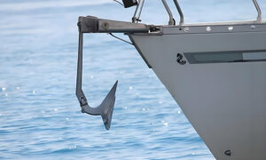
The windlass is a mechanical device for dropping the anchor and is located at the bow of the ship. The rollers on both sides of the sprocket can be used for retracting and releasing cables.
Windlass can be divided into electric, electro-hydraulic and steam windlasses according to their power. At present, the windlasses on sea-going ships are mainly electric windlasses and electro-hydraulic windlasses, and the main structures of the two are basically the same. On some early-built tankers, steam windlasses were also used for fire and explosion protection.
The power source of an electric windlass is an electric motor. Through the gear transmission of the reduction box, the pinion drives the large gear to rotate the load shaft. There is a sprocket on the load shaft. The engagement and disengagement of the large gear and the pinion are controlled by the clutch to control the rotation of the sprocket. In the anchoring operation, when the clutch is disengaged, the main shaft and the reel rotate but the sprocket does not rotate, which can be used for anchoring or twisting the cable. When the clutch is closed, the reel and the sprocket rotate at the same time, which can be used for anchor lifting or anchor delivery in deep water. There is a belt brake on the chain wheel to brake the chain wheel to control the speed of loosening the chain.
Hydraulic windlass, also known as electro-hydraulic windlass, is driven by a motor to drive a hydraulic pump, drive an oil motor, and then run the windlass through a reducer (or without a reducer). It is compact in structure, small in size, stable in operation and good in speed change performance, but requires high manufacturing technology and maintenance.
The steam windlass are driven by a steam engine. The roller shaft is driven by the gear through the crankshaft, the roller shaft drives the sprocket to run through the clutch, and the sprocket is also provided with a braking device. It is characterized by large power and simple structure. When using the steam windlass, the cylinder should be warmed up in advance, and the steam should be drained and released after use to exhaust the residual water vapor in the cylinder. In cold weather, run a sports car (idling the steam windlass) to prevent freezing.
Automatic windlass: There is an anchor chain length sensor in the automatic hydraulic windlass system. When the anchor is thrown out, the windlass will stop automatically; when the anchor is close to the cable drum when the anchor is lifted, it will automatically stop. Slow down, and it will stop automatically when the anchor rod enters the chain drum.
Now there is a windlass that can be operated remotely from the cab. The anchor drop operation can be remotely operated from the bridge.
 1- Motor
2-Reducer
3, 4, 5, 6 – Transmission gear
7-Clutch
8-Sprocket
9-Brake lever
10-Cable reel
11-band brake
Windlass layout
There are two types of windlasses, horizontal windlasses and vertical windlasses. The sprocket shaft of the horizontal windlass is parallel to the horizontal plane. Generally, horizontal windlass are used in general ships; the sprocket shaft of vertical windlass is perpendicular to the horizontal plane, as shown in Figure 3-14. This arrangement can reduce the deck area occupied by the windlass, which is more common on warships.
Some large ships or ships with large bulbous bows often have one windlass on each of the starboard and starboard due to the large distance between the left and right hawse cables.
Main technical requirements of windlass
Main technical requirements of windlass 1. Driven by independent prime mover. The prime mover and transmission shall be provided with protection against excess torque and impact. For the hydraulic windlass, if its hydraulic pipeline is connected with other deck machinery pipelines, the normal operation of the windlass shall not be affected. For ships whose anchor weight does not exceed 250kg, if the manual windlass is suitable for its use, the manual windlass can be configured, and the manual windlass shall have measures to prevent the handle from injuring people.
2. The windlass should have sufficient power and should be able to work continuously. Its workload is:
Al grade gear chain 37.5d2,N
A2 grade gear chain 42.5d2,N
A3 grade gear chain 47.5d2,N
Where: d—diameter of anchor chain, mm.
During the test on board, the windlass shall be capable of pulling up an anchor from a water depth of 82.5m to a depth of 27.5m at an average speed of not less than 9m/min.
3. Under the rated speed of the rated tensile force, it should be able to work continuously for 30 minutes, and should be able to work continuously for 2 minutes under the action of an overload tensile force not less than 1.5 times the rated tensile force (no speed required). The windlass shall also be provided with an overload protection device, which can be turned to medium speed operation when overloaded.
4. The sprocket or drum of the windlass should be equipped with a reliable brake. After the brake is tightened, it should be able to withstand the static tension of 45% of the breaking load of the anchor chain or wire rope, or bear the maximum static load on the anchor chain. The stressed parts should not have permanent deformation, and the braking device should not slip. A clutch should be installed between the sprocket of the windlass and the drive shaft, and the clutch should have a reliable locking device. Brakes and clutches should be easy and reliable to operate. The windlass installation shall be fitted with an effective chain brake. The chain stopper should be able to withstand the test load equivalent to the anchor chain, and its stress should not be greater than 90% of the yield point of its material. When the windlass is running, it should be able to rotate smoothly and quickly.
5. The installation of the windlass should generally ensure that the three points (anchor chain drum, chain maker and sprocket) drawn out by the anchor chain are in a line.
Working load: refers to the tensile force measured at the point where the chain pulley exits the chain. Overload tension: refers to the short-term overload capacity necessary for the windlass.
Average speed: refers to the speed at which the two-section anchor chain is recovered when the three-section anchor chain enters the water and is free-hanging.
Support load: refers to the maximum static load on the anchor chain that the anchor chain wheel brake should be able to bear.
Windlass installation requirements and inspection methods
The anchorage of the windlass shall be welded on the windlass deck according to the position in the drawing, and the welds shall conform to the dimensions specified in the drawing. The surface should be smooth and free of defects such as cracks, missing welding, welding flashes and arc craters. After the gasket reinforcement plate on the machine base is welded, it should be plane processed, and the outward inclination is required to be less than 1:100. The plane should be checked with a flat plate for color oil inspection, and the contact surface should not be less than 60%.
When the windlass is installed, the gaskets between the windlasses should be fitted well. Before the anchor bolts are tightened, use a 0.05mm feeler gauge to check the gap between the upper and lower contact surfaces of the gaskets, and the insertion depth is required to be no more than 10mm. Gasket plane color oil contact surface should not be less than 60%.
When the bracket bearing at the end of the winch cable drum is positioned and installed, after the bracket bearing base gasket is fitted, the clutch center should be calibrated, and the clutch plane deviation and outer circle deviation should not be greater than 0.1mm; open the upper cover of the bracket bearing, use a feeler gauge Check the clearance on both sides of the bearing, the clearance on both sides should be basically the same. The underside of the bearing bush should be in contact (or use a 0.03mm feeler gauge to inspect the underside of the bearing, and it should not be inserted). If the gasket inspection meets the above requirements, it can be considered that the positioning of the bracket bearing meets the requirements. After the windlass gasket is qualified, tighten all the Base bolts and install double nuts.
The base of the windlass should also be installed with lateral gaskets, the slope of the inverted gaskets and the construction inspection requirements are the same as those of the machine base gaskets, and the lateral gaskets should be welded and fixed after passing the inspection.
Test of windlass
First, check whether the installation position of the windlass is correct, and carry out various tests according to the requirements of the windlass, then carry out the anchor drop test at the pier, and finally carry out the anchor drop test at sea. The specification requires that the water depth of the deep-water anchor throwing test is greater than 82.5m, and the average speed of lifting a single anchor should not be less than 9m/min between the depth of 82.5m and the depth of 27.5m. When the anchor chain is released quickly, test the brake 2 to 3 times, and the anchor chain should not slip out, skip the chain and cannot be stopped on the sprocket. After the anchor has been dropped, the chain brake is installed, and the boat is slowly reversed for a while to check the efficiency of the chain brake. Check the fit of the moor to the hull. The installation of the windlass should generally ensure that the three points of the anchor chain (anchor connecting tube, chain controller and chain wheel) are in a line.
The technical indicators of the windlass
The main technical indicators of the windlass include the diameter of the anchor chain, the nominal speed of the anchor, the rated load, the supporting load, several levels of speed change, electrical system, etc.
The installation of the windlass on the ship should ensure that the wrap angle between the anchor chain and the sprocket is 117-120 degrees.
Inspection and maintenance of windlass
Always check whether the brakes are good, whether the clutch is light and flexible, and frequently refuel to ensure that it runs in a good lubricated environment. Special attention should be paid to the lubrication of the friction surfaces of the parts; the oil in the reduction box should be checked and replaced regularly to ensure its cleanliness. The teeth of the sprocket are prone to wear, and the limit is specified to be no more than 10% of the original thickness. If it is found that there are sliding chains and skipping chains, it should be welded and repaired in time; the fastening bolts and the base of the anchor windlass should be checked for looseness and corrosion, and if there are defects, they should be repaired in time. The erosion loss of the anchor base should generally be less than 25% of the original thickness. Except for the base, it should generally be checked once every 3 months.
Electric windlass control circuit
1. Electric windlass towing requirements and characteristics of control lines
Windlasses and winches are usually made into linked units, which can be used for anchoring and lifting, and can also be used as mooring cables. Generally, there are certain requirements for the electric traction of the windlass, such as:
1) There should be an automatic step-by-step delay start link in the control circuit.
2) The motor must have soft or falling mechanical properties, and the motor should be able to withstand the locked rotor for 1min. The stall torque should be twice the rated torque.
3) The motor should be able to start under the maximum load torque. When the anchor is lifted in an emergency, the motor should be able to start normally, and should be able to hold the anchor 25 times within 30 minutes.
4) When breaking down in deep water, the control system should enable the motor to work in the state of regenerative braking or energy consumption braking, so as to realize the change of variable speed break down into constant velocity break down.
5) The control system should be able to meet the requirements of the normal anchoring depth, the average speed of single anchor is not less than 12m/min, the double anchor is not less than 8m/min, and the anchor entry hole is generally about 3m/min.
6) The control system should use electrical and mechanical brakes to meet the requirements of fast stopping and motor protection.
7) It should be able to meet the requirements of double anchors after single anchor is unearthed in a given navigation area.
8) The anchor lifting equipment is required to be light in weight, low in cost, smooth in speed regulation, simple in control and easy to operate.
There are also certain characteristics on the control line, such as:
1) Use the master controller to switch on the relay and contactor to control the forward rotation, reverse rotation and speed regulation of the motor.
2) When the handle of the master controller is suddenly turned from zero to high gear, the control circuit should have an automatic start link.
3) The control circuit should be adapted to the requirement that the motor is locked for 1 min.
4) When breaking down in deep water, the control circuit should have links of regenerative braking and energy consumption braking to achieve constant velocity breaking down.
5) The control circuit should have short-circuit protection, voltage loss protection, overload protection and other protection links.
6) The control circuit should have a braking link that cooperates with electricity and machinery, so that it can stop quickly.
2. Electric windlass control circuit
The control circuit is a reversible symmetrical control system, which uses the master controller to control relays and contactors to start, stop and reverse the motor.
The motor adopts a three-speed squirrel-cage motor with two sets of independent windings: one set is 4-pole high-speed winding; the other set is variable-pole winding, 16-pole low-speed when single-delta connection, and 8-pole when double-star connection is used. Medium speed. The conversion between high speed and medium speed is constant power speed regulation. The medium and low speed stage adopts direct start, and the medium speed to high speed automatically delays the start according to the time principle
When overloaded in high-speed operation, it can automatically return to medium-speed operation instantaneously. After the load is relieved, the main command handle must be turned back to medium speed and then turned to high speed to enter high-speed operation again. The operating current of the overcurrent relay GLJ is 110% of the rated current of the high-speed stage.
In addition, the control circuit has the following protection functions: voltage loss protection, low-speed and medium-speed thermal protection, high-speed overload protection, short-circuit protection, etc.
3. The working principle of the circuit
(1) Start and run
When the power switch DAK and the control circuit power switch LK are closed, the power indicator XD on the master controller is on. When the main command handle is at the zero position, LK1 is closed, the zero-voltage relay LYJ is energized, the contacts (3~5) are closed, the control circuit is energized, and the time relay 3SJ is energized at the same time, and the contacts (51~53) are closed, energizing the ZDQ. Prepare.
Anchor first gear:
When the main command handle is pulled to the first gear of the anchor, LK1 is disconnected, and LK2, LK4, and LK7 are closed. The direction contactor ZC and the low-speed contactor lC are energized, the motor windings are energized in a delta connection, and the ZDQ is energized at the same time, the brake is released, and the motor runs at a low speed. The ZC auxiliary contacts (15~17) are disconnected to realize electrical interlock between ZC and NC, while the ZC auxiliary contacts (59~57) are disconnected, so that the 3SJ is powered off, and the contacts (51~53) are delayed (Not less than 1s) disconnect; make the brake coil ZDQ serially connect the economic resistor R3.
Anchor second gear:
When the main command handle is pulled to the second gear of the anchor, LK4 is disconnected and LK5 is closed. lC is powered off, the medium-speed contactors 2C2 and 2C1 are energized successively, and the motor is energized with a double star connection to run at a medium speed. 2C1, ZC2 and lC are electrically interlocked through their auxiliary contacts. The time relay is energized with 1SJ, and the contacts (33~35) are closed with a delay to prepare for 3C energization.
Anchor third gear:
When the main command handle is pulled to the third gear, LK6 is closed, the intermediate relay OJ is energized, and its contacts short-circuit the coil of the overcurrent relay GLJ, so that the GLJ does not move during the shifting process. The high-speed contactor 3C is energized, the high-speed winding of the motor is energized, and the auxiliary contacts (2~6) are disconnected, and the auxiliary contacts (37~39) are closed, so that the 3C coil is self-locked and 1C, 2C1, 2C2 are powered off, and the motor Run at high speed. At the same time, the time relay 2SJ is energized, and its contacts are disconnected with a delay (when the 2SJ delay is set at the rated load of the motor, the time for the steady-state transition from the medium-speed stage to the high-speed stage is generally 1~2.5s), so that the OJ is disconnected. Electricity, its contacts are disconnected, GLJ will play the role of high-speed overload protection.
When the high-speed stage is overloaded, the GLJ operates, the contacts are disconnected, and the 3C is powered off, so that 2C2 and 2C1 are energized successively, and the motor switches to the medium-speed stage operation. After the 3C is powered off, its self-locking contacts (37~39) are disconnected, so it cannot be powered on by itself after the overload disappears. If high-speed operation is required, the handle must be returned from the third gear to the second gear, and then pulled to the third gear. Row.
The main command handle is quickly turned from the zero position to the third gear of the anchor:
When the handle is quickly turned from the zero position to the third gear of the anchor, 2C2 and 2C1 are immediately energized, and the motor starts directly at medium speed. After 1SJ delay (usually 0.5~2s), 3C is energized and switched to high-speed operation.
When the thermal relays 1EJ and 2EJ are overloaded, the automatic reset time of the thermal relay will take about 2 minutes. In an emergency, when the motor still needs to run at low or medium speed, you can press the emergency button JA on the master controller to make the motor Keep working hard.
(2) Throwing (reverse) and parking
When the main command handle is placed in each gear of the anchor, the working condition is the same as that of the anchor, only the directional contactor NC is used instead of ZC to energize, so that the motor is reversed. When the anchor breaks down in deep water, the motor enters the regenerative braking state under the drag of the anchor weight to realize the constant velocity break down.
When parking, the main command handle is pulled back to the zero position, the power supply of the motor is cut off, the brake is powered off for mechanical braking, and the motor quickly stops running.