Definition of Ship Propeller
1. Two or more blades are connected to the hub, and the blade surface is a helical surface or a marine propeller that is similar to a helical surface.
2. Generally installed at the rear of the ship, there are two or more blades connected to the hub, and the rearward side of the blade is a helical surface or a marine propeller similar to a helical surface.
An introduction to the performance of propeller
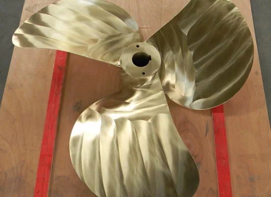
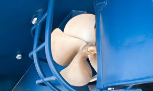
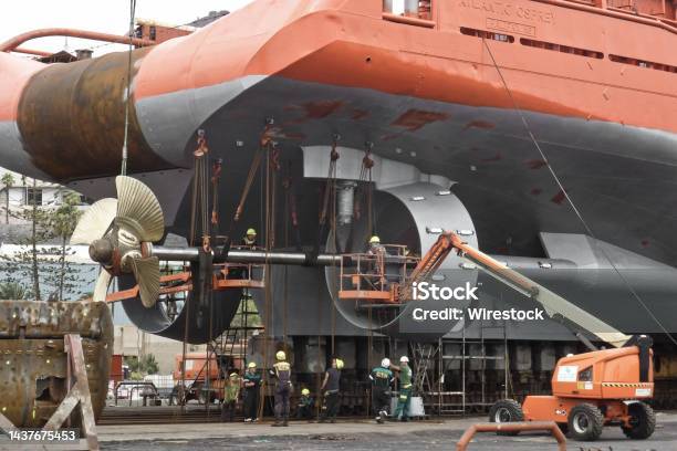
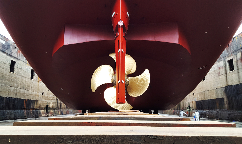
A propeller consisting of a propeller hub and a number of blades radially fixed on the hub, commonly known as vanes. The propeller is installed below the waterline of the stern, and is rotated by the main engine, which pushes the water to the back of the ship, and uses the reaction force of the water to push the ship forward. The ship propeller is simple in construction, light in weight, efficient and protected below the waterline.
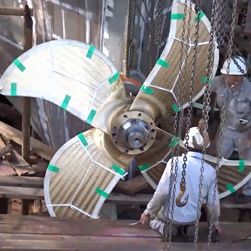
Ordinary transport ships have 1 to 2 propellers. For ships with high propulsion power, the number of propellers can be increased. Large, fast passenger boats have two to four oars. The propeller generally has 3 to 4 blades, and the diameter is determined according to the horsepower and draft of the ship.
The lower end does not touch the bottom of the water, and the upper end does not exceed the fully loaded waterline. The speed of the propeller should not be too high. The speed of the ocean cargo ship is about 100 rpm, and the speed of the small speedboat is as high as 400 to 500 rpm, but the efficiency will be affected. The propeller material is generally manganese bronze or corrosion-resistant alloy, but also stainless steel, nickel-aluminum bronze or cast iron.
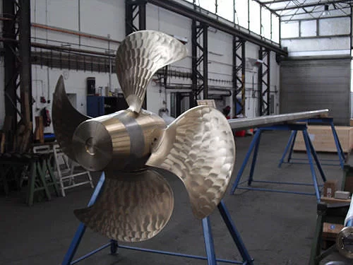
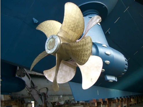
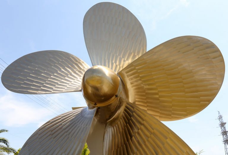
A disk-shaped helical propulsion device that drives a ship forward. It consists of a blade and a hub connected to it. Commonly used are three leaves, four leaves and five leaves. Including single propeller, ducted propeller, counter-rotating propeller, tandem propeller, controllable pitch propeller, supercavitating propeller, large skew propeller, etc. Propellers are generally installed at the stern (underwater).
Marine propellers are mostly made of copper alloys, but also cast steel, cast iron, titanium alloys or non-metallic materials. The research on marine propeller is divided into two aspects: theory and experiment. In theory, there are momentum theorem, blade element body theory, lift line theory, lift surface theory, boundary element method and other theories and analysis methods, which can more accurately predict the hydrodynamic performance of the propeller and carry out theoretical design. The experimental research is mainly to study the propeller performance through model tests, and draw the propeller design map. The design methods of marine propellers are divided into two categories, namely theoretical design methods and map design methods.
Since the 1960s, ships have tended to become larger. After using high-power main engines, problems such as stern vibration, structural damage, noise, and erosion caused by propeller excitation have attracted the attention of various countries. The fundamental reason for the excitation of the propeller is that the load on the propeller blade increases, and local unstable cavitation is easily generated when working in the uneven wake behind the ship, which leads to the constant change of the pressure, amplitude and phase of the propeller acting on the hull.
Types of Marine Propellers
On the basis of common propellers, the following special propellers are developed in order to improve the performance of propeller, better adapt to various sailing conditions and make full use of the main engine power.
Adjustable pitch propeller
Pitch propeller for short, can adjust the pitch according to need, give full play to the host power; Improve the propulsion efficiency, the ship can not change the main engine rotation direction when backward. Pitch is adjusted by mechanically or hydraulically operating a mechanism in the hub that rotates the blades. The adjustable pitch paddle has good adaptability to the change of blade load and is widely used in tugboats and fishing boats. For general transport ships, ship-machine-oar can be in a good matching state. However, the hub diameter of pitch control propeller is much larger than that of ordinary propeller, and the section of blade root is thick and narrow. Under normal operating conditions, the efficiency of pitch control propeller is lower than that of ordinary propeller, and the price is expensive and the maintenance is complicated.
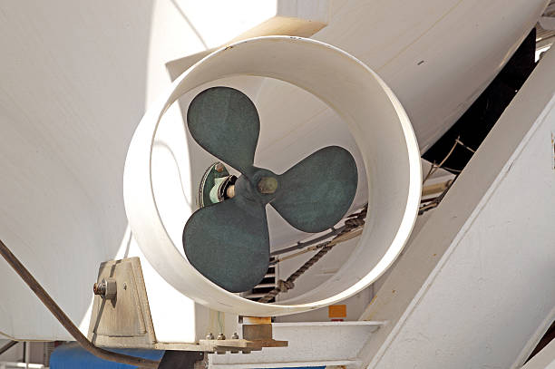
Ducted propeller
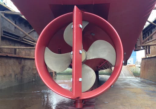
The outer edge of the ordinary boat propeller is fitted with a wing shaped section of the circular duct. This catheter is also known as the Koch catheter. The vessel is fixed to the hull of the vessel, and the vessel is connected to a rotating rudder rod and also acts as a rudder blade. The ducting can improve the propulsion efficiency of the propeller, which is because of the high velocity and low pressure inside the ducting, and the pressure difference between the inside and outside of the ducting forms additional thrust on the tube wall. The clearance between the pipe and the propeller blade is very small, which limits the flow loss around the blade tip. The duct can reduce the wake shrinkage behind the propeller and reduce the energy loss. But the astern performance of the ducted propeller is poor. Fixed ducted propeller can increase the ship’s turning diameter, and the rotating ducted propeller can improve the ship’s turning performance. Ducted propellers are mostly used to push boats.
Tandem propeller
Two or three ordinary propellers are mounted on the same shaft and turn in the same direction at the same speed. When the propeller diameter is limited, it can increase the blade area and absorb higher power, which is beneficial to vibration reduction and cavitation avoidance. Tandem propellers have larger weight and longer propeller shaft extension, which increase the difficulty in layout and installation and are seldom used.
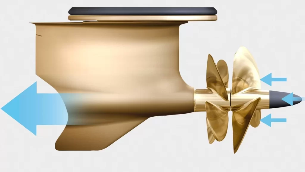
Counter rotating propeller

Two ordinary propellers are mounted on concentric inner and outer shafts respectively, rotating in opposite directions at constant speed. Because it can reduce the wake rotation loss, its efficiency is slightly higher than that of a single propeller, but its shafting structure is complex and has not been applied in large ships. (5) Straight blade propeller: composed of 4 to 8 vertical blades. The upper straight blade propeller disc, blade uniform along the peripheral disk installed, the disc into the bottom flush with the hull plate, the disc rotates, blade besides around the spindle rotation, also vertical shaft system of swing around itself, resulting in a different direction of thrust, so can make the ship to turning in place, don’t have to use the rudder steering, also don’t have to change the host when the ship back to. However, due to the complex mechanism, high price and easy damage of blade, it is only used for a few harbor ships or ships with special requirements on handling performance.
Propeller mounting method
There are two ways to install the propeller on the shaft, one is keyless installation, the other is keyless installation.
With the continuous development of shipbuilding technology, the keyless installation of propeller and shaft can avoid the stress concentration of shaft caused by machining keyway on propeller shaft, so more and more ships use keyless installation of propeller and gradually replace keyless installation. Keyless hydraulic sleeve mounting propeller method, as shown in figure. The propeller is set on the stern shaft, and the hydraulic nut is installed. The high-pressure oil pumped by the oil pump enters the stern shaft and the conical surface of the propeller through the oil groove of the inner hole of the propeller hub through the high-pressure oil pipe, so that the propeller hub produces elastic deformation and is expanded. At the same time, high pressure oil is supplied to the hydraulic nut, which generates forward thrust and makes the propeller move forward. When the propeller is pushed to the specified position, the high pressure oil of the cone hole of the propeller hub is put first, and then the high pressure oil of the hydraulic nut is released. Due to the recovery of the elastic deformation of the propeller hub, the propeller is closely matched on the stern shaft.
Marine propeller installation method improved
1. Ship high-speed, energy-saving, bidirectional force propeller placement method
“High speed energy saving bidirectional force propeller placement method” is a different placement scheme proposed on the basis of the existing propeller technical structure. Because the existing method of oar placement can only make the oar produce unidirectional force and single function, which makes the oar play less than half of its due effect, waste more than half of the energy and make the ship speed too low; The invention can make the oar produce bidirectional multifunctional force, give full play to the potential of the oar, and greatly improve the speed and energy saving. The paddle is arranged in a pipe, the pipe through the hull before and after, its inlet in the bow, the outlet in the stern, when the paddle turns to action, the water in front of the ship through the inlet quickly pumped to the stern into a recoil force. On the other hand, when the oar flows in front of the suction vessel, its inlet can also produce a low-pressure traction force.
2, large ship propeller vertical pre-installation device
Large ship propeller vertical pre-installed devices, including base, spreader, described the base composed of panel, plate, plate, pipe and board composition, adjusting panel layout with the propeller when propeller pre-installed tighten bolt hole at the base, supporting tube and vertical plate are at least four match, respectively arranged between the panel and the plate, The upper end and lower end of the supporting tube are respectively fixedly connected with the panel and the seat plate, one side of the vertical plate is fixedly connected with the supporting tube, the upper end and lower end of the vertical plate are respectively fixedly connected with the panel and the seat plate, and a plurality of adjusting plates are arranged on the seat plate, each adjusting plate is installed on the adjustment screw adjustment base level. The lifting device is composed of a flange, a lifting lug and a strengthening plate, the lifting lug is fixedly connected with the flange, the strengthening plate is arranged on both sides of the lifting lug, the strengthening plate is fixedly connected with the flange and the lifting lug, and the bolt hole on the flange is the same with the bolt hole of the pre-installed stern shaft flange.
The utility model has the advantages of simple device structure, strong field operation and safe pre-installation.
3. Installation device between large propeller shaft and stern tube
The utility model relates to an installation device between a large propeller shaft and a stern tube with small clearance on a large ship, which consists of a longitudinal track bracket , a longitudinal track and a trolley placed on the longitudinal track . The trolley is composed of longitudinal walking wheel , fixed bracket , lateral limit bar, upper and lower movable bracket, upper and lower adjusting screw, sliding plate, left and right adjusting screw and gasket. The longitudinal walking wheel is arranged on the fixed bracket, and placed on two longitudinal rails, the lateral limit bar is arranged on the top of the two longitudinal rails, the upper and lower movable bracket is arranged above the fixed bracket, and the fixed bracket with two up and down adjusting screw connected, the slide plate has two, Each one is placed on the left and right two movable brackets , and the left and right two movable brackets are respectively connected with two adjusting screws, and the gasket has two pieces, respectively placed on the left and right two sliding plates on the top of the inclined plane. The utility model is simple, reliable and practical.
4. Adjustable propeller with integral guide frame
The utility model relates to an adjustable propeller with an integral guide frame, which comprises a propeller hub, an oil cylinder, a piston, a guide frame, a blade root, a slider and a stern shaft. The guide frame is formed by a hollow shaft passing through the center of a cube, and the four corners of the cube are respectively provided with a crank pin. One end of the hollow shaft is connected with the piston, the other end is connected with the inner hole of the stern shaft; The blade coil is provided with a guide groove, and the crank pin on the integral guide frame is arranged in the guide groove of the blade coil through the slide block.
Its advantages are: because of the use of integral guide frame structure, can reduce the number of parts and the amount of machining and shipping inspection costs, enhance the reliability of parts; Because there is a guide groove instead of a crank pin on the blade coil, the blank size of the blade coil is reduced, the cost is reduced, and the rough machining is reduced. The whole guide frame makes the installation of the whole adjustable propeller more convenient.
Marine propeller structure improvement
1. Double-flow propeller
The utility model relates to a efficient propeller which can be used both as a propulsion propeller for ships and for other similar applications. Comprises a plurality of blades (1), wherein a plurality of blades (1) are fixed on the outer wall of a concentric water cylinder (2), and a plurality of inner blades (4) are arranged between the inner wall of the water cylinder (2) and the hub of the propeller (3). The inner blade (4) provided in the water cylinder (2) is opposite to the spiral direction of the blade (1). The utility model adopts a structure in which a water cylinder is arranged in the vortex region of the propeller hub, and a plurality of inner blades with opposite rotation direction of the blades are arranged between the inner wall of the water cylinder and the hub of the propeller.
When use, propeller turn up and push back water, the water of the water in the cylinder is forward flow, thus improving the conditions of low pressure water in front of the propeller, limiting its hub area appear vortex, strengthen the wake behind the propeller, increase the reaction force of propeller, so as to improve its use efficiency, in order to improve the speed of the ship.
2, Marine efficient and powerful propeller
The utility model relates to a Marine efficient and powerful propeller, which is mainly composed of a wheel hub and a plurality of blades. The surface of the paddle striking water is provided with a convex line crow’s feet and is made into an integral rough surface. The blade is made of metal material, and a layer of tire rubber surface is composite on the water striking surface of the metal blade, and the tire rubber surface is provided with convex line crow’s feet and is made into an integral rough surface.
It has the characteristics of simple structure, convenient and reliable use, increasing the propulsion power of the ship when the propeller is used, usually the thrust of the propeller increases by 15 ~ 30%, and can achieve the effect of silence.
3. Circular combined propeller
Circular combined propeller consists of propeller hub, connecting blade (helical blade), rotor, etc. The connecting blade (spiral blade) directly connects the hub with a ring, and radiates outward to set the rotors on the basis of the ring. The more rings are set, the more additional rotors are added. This propeller can set more rotors within the same radius of rotation, and get a larger push and pull force. The propeller can be used in aircraft, helicopters and ships.
4. Adjustable pitch propeller device

An adjustable pitch propeller device, including hollow hub, described in the hollow hub on the radial uniform several blade, blade joins in a week through the hub wall bearing hole and into the hollow cavity within the hub of short axis, described in the hollow cavity within the hub operates can drive the blade at the same time into the short axis rotation to adjust the blade Angle of the transmission structure.
The device can not only adjust the working Angle of propeller blade according to different working conditions, so as to improve the utilization rate of engine output power and the service life of the engine, but also has simple structure and low cost.
5. Propeller structure and manufacturing method for high-efficiency ships
The utility model relates to an efficient ship propeller structure and a manufacturing method thereof, which comprises a propeller billet body, the material of which is light metal material; The surface of the propeller body was ceramicized to form a kind of ceramic layer. A low resistance layer is formed on the surface of the ceramic layer.
This method can provide the propeller with the mechanical properties of light weight, high strength, corrosion resistance and low friction, and has the characteristics of energy saving, low cost and long service life.
6, Ship high speed energy saving bidirectional force propeller
The utility model relates to a high speed and energy saving bi-directional force propeller, in which a propeller sleeve is arranged under the surface of the bow, and the inlet of which leads to the ship from the bow; A propeller is arranged in the part near the bow of the propeller sleeve. After the propeller sleeve is extended from the inside of the ship for a certain distance, it is extended to the left and right sides of the propeller sleeve for the left branch pipe and the right branch pipe of the propeller sleeve. The water outlets on the left and right sides of the left branch pipe and the right branch pipe respectively lead to the outside of the ship from the left and right sides.
By optimizing the propeller setting mode and the installation position of the ship, the driving effect of the propeller is doubled compared with the existing one-way propeller, and the sailing distance is doubled and the speed is doubled in the same time.
7. Marine copper alloy propeller and tail shaft blowing device
A Marine copper alloy propeller and shaft brushed with device, a four small platform at the bottom of the working platform and brushed with stents welding, plate connected to the working platform, the base plate through the channel steel connection with brushed with stents, jack in the middle of the floor, work platform with fastening screw holes, lighten the light hole, middle shaft hole, composed of four columns and brushed with stents channel steel welding. When the utility model is working, the propeller is installed on the working platform, the tail shaft is lifted and placed in the middle hole of the propeller, the propeller is fixed, and the tail shaft moves up and down under the action of the jack to carry out the blowing match between the propeller and the tail shaft.
Reasonable structure, firm and reliable, simple operation and long service life can not only improve the precision of propeller and tail shaft mixing, but also improve the efficiency of propeller and tail shaft mixing. The device has been widely used in 57000T, 53100T, 53500T, 53800T, 16500T propeller and tail shaft blowing match.
8. An efficient and energy-saving propeller for Marine
The utility model relates to a Marine propeller with high efficiency and energy saving, which comprises a hub and a blade connected with the hub, and the hub is provided with at least one communicated hole connecting the front annulus of the hub and the rear annulus of the hub; The aperture of the rear end of the connected hole is larger than that of the front end; A groove is arranged between two connected holes on the front surface of the hub; Grooves increase in width from one end to the other and decrease in depth; The hub is provided with a weight reduction hole; The width of blade surface is greater than that of blade back. The invention provides a Marine high efficiency and energy saving propeller. When the propeller is working, the water at the high pressure in front of the propeller hub can directly enter the low pressure area behind the propeller hub through the connected hole, so that the two areas are connected, the pressure in the low pressure area is increased, and the pressure between the two areas is basically balanced, greatly improving the efficiency of the propeller. The trumpet-shaped shape at the rear end of the connected hole can make the water flowing out of the hole collide with the linear water flow to form the water flow acting on the inclined plane of the blade along the edge, thus forming the auxiliary force driving the propeller blade to operate.
Marine propeller control method or system
1. Propeller turning device
Propeller turning device, including upper bracket, lower bracket, intermediate shaft and nut. The bottom of the intermediate shaft is fixedly connected with the lower bracket, the upper part of the intermediate shaft is made into a wedge shape and is provided with a thread on the round surface, the thread is matched with the nut, and the top and bottom ends of the intermediate shaft are respectively provided with an upper lifting lug and a lower The lifting lug, the middle part of the upper bracket is provided with a forming ring hole that matches the wedge-shaped part of the intermediate shaft, the upper bracket is sleeved on the wedge-shaped part of the intermediate shaft with its forming ring hole, and the nut is screwed on the intermediate shaft and passes through The washer is pressed on the upper bracket to form the propeller turning device.
After boat propeller is installed in the upper and lower brackets, it is pressed with a nut, and the sling does not touch the propeller when it is lifted and turned over, which completely eliminates the damage to the propeller and the phenomenon of the sling being cut off, and changes the original screw to turn over. The hoisting method is an innovative technological transformation of the blade turning over. It has strong practical value for batch shipbuilding and specialized shipbuilding.
2. Control method and control system of controllable pitch marine propeller
A method of controlling the pitch of a controllable-pitch marine propeller of a watercraft having an engine, comprising the steps of: providing a power stop mode to rapidly reduce the speed of the boat as the watercraft advances; and adjusting the propeller pitch to a fully reversed position while engine power is at Available throughout the transition of the vessel from forward motion to the vessel’s reduced forward speed. The present invention also discloses a system for controlling the pitch of a controllable pitch marine propeller of a vessel including an engine, comprising: a drive actuator movable from a forward position to a reverse position; a controller for adjusting the pitch of the propeller so that the The pitch is in the fully reversed position; and wherein the controller determines the power stop requirement by monitoring the movement of the actuator, and is used to adjust the propeller pitch to the fully reversed position based on the determination of the power stop while the engine power is being transferred from the forward movement of the vessel to Available the entire time the boat is slowing down.
3. A propeller lifting and reversing device
A propeller lifting and reversing device, the propeller is connected with the lower end of a lifting rod, the lifting rod is arranged in a rotating sleeve, and the setting method of the lifting rod and the rotating sleeve is as follows: the lifting rod can move up and down in the rotating sleeve, and the lifting rod is connected with the rotating sleeve. The rotating sleeves cannot rotate with each other. The rotating sleeve is movably arranged in the fixed sleeve located at the stern. The upper end of the rotating sleeve protrudes from the fixed sleeve. The rotating sleeve extending from the fixed sleeve is provided with a steering rod. The upper end of the lifting rod is connected with the piston rod of another hydraulic oil cylinder fixed on the rotating sleeve through the connecting support.
The advantages are: this boat propeller lifting and reversing device can make the propeller lift and reverse quickly, remove the garbage or sundries wrapped around the propeller, easy to operate, high degree of mechanization, and ensure the normal sailing of the water surface clean collection vessel. and homework.
4. Control method and control system of controllable pitch marine propeller
A method of controlling the pitch of a controllable-pitch marine propeller of a vessel including an engine, comprising: providing an indication of a vessel’s speed; using the vessel’s speed to control engine power according to any one or more parameters selected from the group consisting of: the propeller: Pitch and mode of operation of the vessel.
A system for controlling the pitch of a controllable pitch marine propeller of a vessel including an engine, comprising: a speed device for providing an output indicative of the speed of the vessel; for using the output according to any one or more parameters selected from the group consisting of A controller that controls the power of the engine, these parameters include: propeller pitch and the boat’s operating mode.
5. A method and device for actively controlling the thrust pulsation of a ship’s propeller
A method and device for actively controlling thrust pulsation of a ship propeller, measuring the pulsation of the axial thrust of the ship propeller or the axial vibration of the propulsion shafting through an axial thrust or axial vibration measuring system installed on the propulsion shafting of the ship According to the axial thrust pulsation of the propeller or the axial vibration of the propulsion shafting, the thrust pulsation controller calculates the size of the control force that needs to be exerted on the propulsion shafting of the ship in order to eliminate the thrust pulsation, and then passes the power The amplifier amplifies the signal of the thrust pulsation controller, and then generates the required axial control force on the ship’s propulsion shaft through a non-contact electromagnetic force actuator installed on the ship’s propulsion shaft, so as to control the ship’s propulsion. The propeller thrust pulsation is controlled and compensated, so as to reduce the influence of the ship propeller thrust pulsation on the boat vibration.
Other Marine propeller related equipment
1. Ship contra-rotating propeller propulsion device
The ship contra-rotating propeller propulsion device is a kind of ship propulsion device with high efficiency and energy saving, which can adapt to various kinds of power and types. The device through the cabin engine directly drives the transmission ratio range (3:1 ~ 40:1) a straight way.
The other parts all symmetrical arrangement, high transmission efficiency, stable transmission, organization is compact, low vibration noise. It can automatically adjust and overload protection ability, and can complete the positive and reverse at the same time, slow down and dynamic shunt three big functions of counter rotating gear box, A novel, high efficiency, energy saving and environmental protection antirotating propeller propulsion device is composed of antirotating gear box directly matching with two antirotating propellers with remarkable energy saving effect.
It can fully absorb the wake rotation energy loss caused by a propeller to achieve fuel saving of 10 ~ 15%, and improve the propulsion efficiency and ship speed by more than 10%.
2. The invention relates to a propeller driving device for a ship
A ship propeller drive, drive shaft and coaxial fixed set on the drive shaft of the first collar. The collar on the fixed set has a more uniform distribution of the first pole, drive shaft and shaft sleeve is equipped with a second shaft sleeve. The second shaft sleeve and set against the side of the first shaft sleeve, the second shaft sleeve on a fixed set with the first brace corresponds to the second support bar. A flexible blade is arranged between the first support rod and the second support rod. Each flexible blade is arranged in the same direction, the driving shaft is provided with an axle sleeve reversing drive device.
Advantage is that when meet danger situation in need of urgent back, as long as the direction of the flexible blade with the original in the opposite direction, can make whole propeller device inversion. The whole process is very short, and don’t need to be positive and negative to the transformation of the propeller can achieve the goal of reverse drive the ship, eliminating the middle interval, can make the ship quickly retreat, A possible accident was avoided.
3. Install the hydraulic roof of the marine propeller
A propeller hydraulic roof installation, the hydraulic top include oil cylinder and the plunger plunger described form work oil cavity insert inside the cylinder, piston within the cylinder of the trip is about 15 ~ 20 mm, between the plunger and the cylinder touching part described a seal groove, the sealing groove is equipped with the function of aprons, on the ontology of oil cylinder set with two holes, one is the oil inlet, The other is the exhaust port.
For repairing the shipyard’s key equipment – the dock, the production schedule is by the hour. The use of the hydraulic roof can advance the dock time by at least half a day. Through the practice test, the installation of propeller hydraulic roof is very convenient to use, save time and labor, the price is 60% lower than the imported hydraulic roof.
4. Automatic cutting device for propeller winding
A propeller winding automatic cutting device comprises a cutting tool, which is characterized in that the cutting tool is installed on the outer wall of the ship stern tube and crosses the slot between the ship stern tube and the propeller propeller drum, and the cutting tool is provided with a blade toward the end face and the outer side of the propeller.
The automatic cutting device of propeller winding can cut the winding automatically by the rotation of propeller. It has simple structure, thorough cutting and high efficiency, and can be applied to various ships to prevent the failure caused by propeller winding.
5, Marine underwater telescopic, full rotation electric propeller propeller sealing device
It relates to Marine equipment, especially the propeller sealing device of underwater telescopic and full rotary electric propeller of multi-functional semi-submersible ocean engineering ship. It includes installed on the shaft sleeve by at least one lip is synchronized to the rubber sealing ring and clamping fixed up of the lip is synchronized to the rubber sealing ring seal seat lubrication sealing device and composed of installed in air sacs in the rubber balloon waterproof bag sealing device, bush also install set by relative and mutual joint of ring and static ring end face sealing device, The shaft sleeve is also provided with an oil-proof airbag sealing device composed of a rubber airbag installed in the airbag seat.
The device can seal properly in deep water to ensure the normal operation of the electric propeller.
6, Marine adjustable propeller vertical hydraulic power unit
The vertical hydraulic power unit of Marine adjustable propeller comprises a fuel tank, Marine hydraulic pump, filter, valve block group and cooler. The characteristics lie in that the hydraulic pump and valve block group are placed on the top or side of the fuel tank, the filter and cooler are vertically installed on the side of the fuel tank, and an oil pan is welded below the filter.
The hydraulic pump adopts vertical electric hydraulic pump and cooler vertical tube cooler. The valve block group adopts double hydraulic control one-way valve, shuttle valve, electro-hydraulic proportional directional valve and valve body superimposed in series from top to bottom. The hydraulic pump and valve block group are placed on the top of the tank, which effectively makes use of the relatively surplus space in the height direction of the engine room. Relatively improve the effective maintenance and operation space of the host and other equipment; Because the filter is provided with an oil pan, it can ensure that when replacing the filter element, the hydraulic oil retained in the filter cylinder will not flow to the engine room ground, causing environmental pollution.